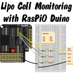
I Want an Easy to Use Lipo Battery Voltage Meter for My Workshop
I've been using lithium polymer (lipo) batteries since 2006, when I nervously shelled out £30 for a 3 cell 1600 mAh 10C HiModel lipo to power my EasyStar RC plane. I also spent about the same on a charger and balancer for it. Thankfully, all these things have come down a lot in price since then. I don't think I'd expect to pay much more than £10 for an equivalent battery now.
Typical lipo batteries for large devices have multiple cells. A lipo cell has a no-load resting voltage of 4.2 V when fully charged and 3.7 V when discharged (you can take them a bit further, but they don't last as many cycles).
It's important that the cells within a battery are fairly evenly balanced, which is why most multi-cell lipos either have balancing circuitry built into them (e.g. laptop battery) or balance ports attached (e.g. RC planes)…
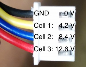
JST-XH connector showing cell voltage maxima
It just so happens that the commonly used JST-XH balance port connectors are the same size and spacing (0.1 inch) as the standard pinout on many PCBs. This is useful because it means we can use standard breadboarding wires to make connections – and even standard pin headers if we make a permanent stripboard attachment.
I have a little device that plugs into a lipo balance port and uses a 7 segment display to show the voltage of each cell in succession. It looks something like this one…
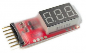
Lipo Meter on Ali Express
But for a number of years I've had a hankering to make one of my own. I've been working on my RasPiO Duino lately and decided it was time I got on with this little project. The lipo gauge I use has a tiny Atmel microcontroller on so the Duino's ATMEGA328P-PU is more than up to the task.
Before We Start The Explanation
This project is quite complex compared to the examples that come with the RasPiO Duino. If you backed the RasPiO Duino KickStarter, you will be getting a much gentler introduction than this. With this post, I'm just doing what I tend to do on RasPi.TV, which is to blog "what I'm doing right now". It's not intended to be part of the RasPiO Duino materials, but could be considered an extra.
OK. Let's get on with the explanation…
The Main Problem?
The biggest issue is that we are running the RasPiO Duino at 3.3 V, so the maximum Voltage we can measure with the onboard analog ports is 3.3 V. The balance port on cell 3 can reach 12.6 V, so we need a way of reducing this to <= 3.3 V. It just so happens that we can use a neat little electronics trick called a voltage divider or resistor divider. Who said resistance was futile? [caption id="attachment_7881" align="aligncenter" width="695"]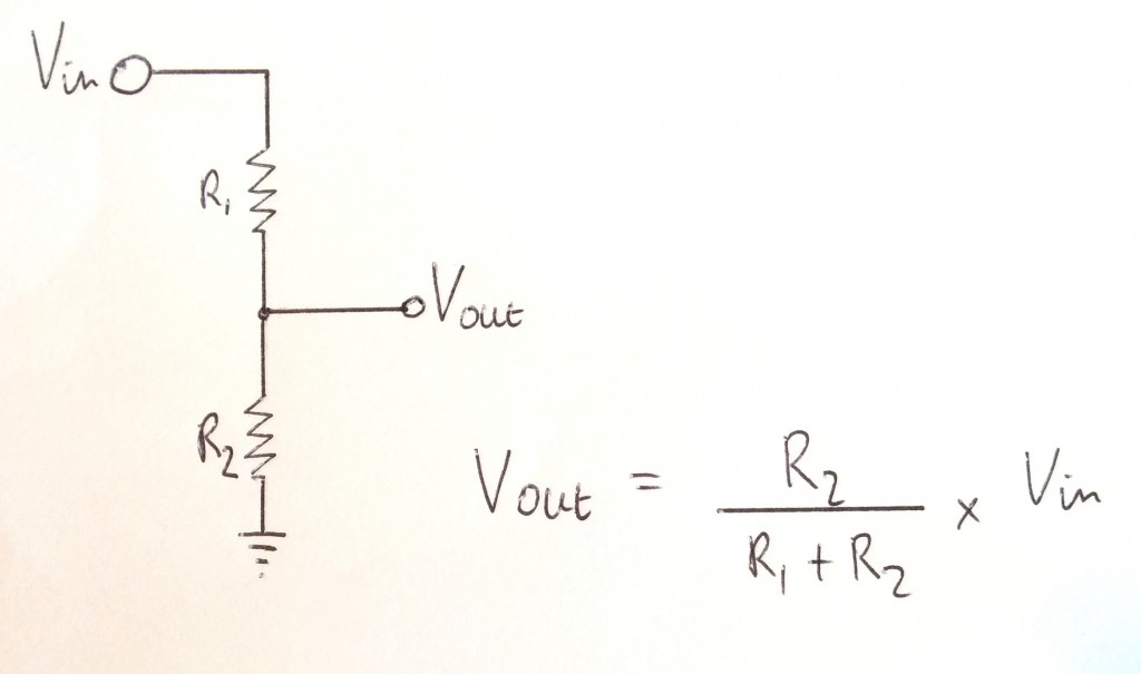 Resistor divider for reducing our input voltage[/caption]
Yuck – Maths!
It's not that bad actually. It follows Ohm's law (Current = Voltage / Resistance, I = V / R) and allows us to choose resistor values that will adjust the voltage down to whatever we want. The proportion on the R2 side is 'thrown away' to GND and the other proportion goes to Vout.
I don't like wasting battery power, so decided to use 10 kΩ resistors for R2. This means that we're only wasting 3.3 V / 10,000 Ω = 0.00033 Amps, or 0.33 milliAmps to GND for each cell (1 mA total).
In an ideal world, we'd want to reduce all three of our maximum input voltages to exactly 3.3 V, to make full use of the ATMEGA's 0-3.3 V measurement scale, but sometimes you have to compromise a bit, according to the stock of resistors you actually have.
Cell 1 dropping 4.2 V to exactly 3.3 V would require R1 = 2.725 kΩ
Cell 2, dropping 8.4 V to exactly 3.3 V would require R1 = 15.45 kΩ
Cell 3, dropping 12.6 V to exactly 3.3 V would require R1 = 27.9 kΩ
In practice, you want to err on the high side of resistance (lower voltage), so I picked the next highest that I had available in each case…
3.3 kΩ
18 kΩ
30 kΩ (I used a 10kΩ and 20kΩ in series)
This means that our maximum Vout values should be…
4.2 * 10 / 13.3 = 3.16 V
8.4 * 10 / 28 = 3.00 V
12.6 * 10 / 40 = 3.15 V
…but we can apply a correction (and calibration) in software, later on, to calculate the right values. But let's not get ahead of ourselves. There's a circuit to build first…
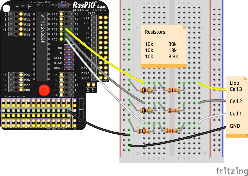
RasPiO Duino lipo monitor circuit
Here's what the real thing looks like. Since we're using an HDMIPi monitor, we can display all three cell Voltages at once…
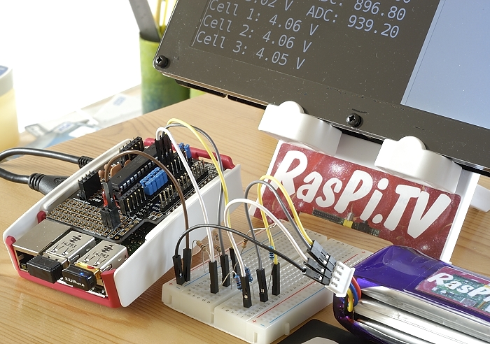
Breadboard circuit for voltage divider with RasPiO Duino
And once I had proof of concept on the breadboard, I made a permanent version on a small scrap of stripboard I had lying around. It could have been about 6 holes shorter, but meh!
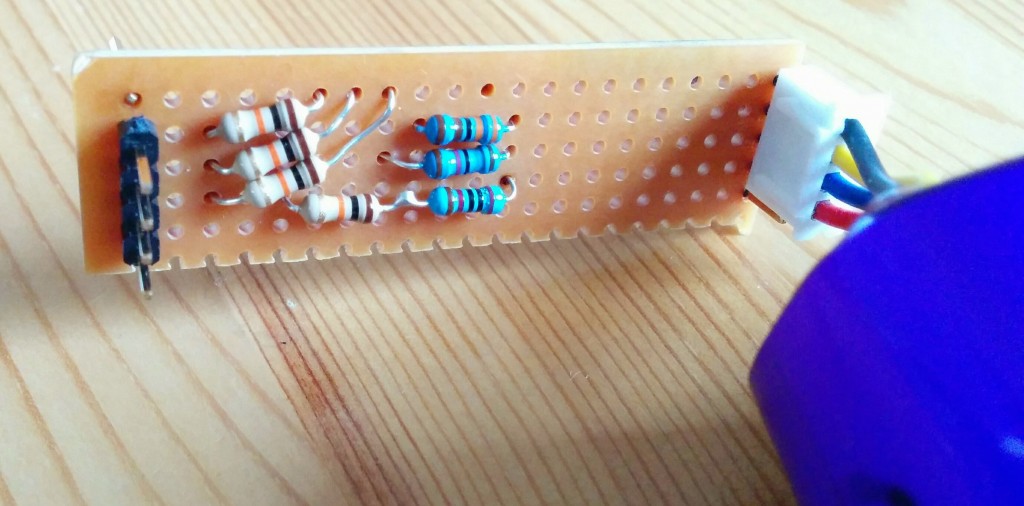
Stripboard version of voltage divider
And here's a view of the whole stripboard version with full on-screen output. First three lines are raw output from the Duino, next three lines are processed by the Pi in Python…
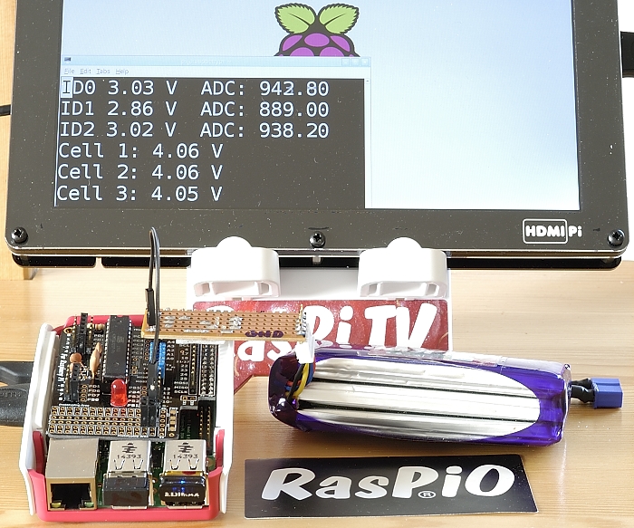
RasPiO Duino stripboard voltage divider for lipo monitoring
The stripboard version eliminates 7 out of 8 of the jumper wires, which makes it much simpler to use (as long as you keep your wits about you and plug the lipo in the right way round – note the large GND label).
So How Does It Work?
The RasPiO Duino is programmed to read analog ports A0-A2 six times. It discards the first reading, then averages the next five. The reason for chucking away the first reading is that it's sometimes inaccurate (it's something to do with multiplexing and capacitors that I once read about in the Adafruit Forums). It doesn't cost us anything and doesn't take very long, so I like to do it.
// RasPiO Duino lipo monitoring void setup() { Serial.begin(9600); //Start serial connection with computer } void loop() { // read analog pins 0-2 and report results by serial for (int adcPin = 0; adcPin < 3; adcPin++) { analogRead(adcPin); // first adc reading is discarded delay(20); int reading = 0; // now we read the pin 5 times for (int loop = 0; loop < 5; loop++) { reading += analogRead(adcPin); // add each value delay(20); } // now divide by 5 for average and convert to a voltage float voltage = reading * 3.29 / 5.0; voltage /= 1023.0; float adc = reading / 5.0; // send output to Pi through serial port Serial.print("ID");Serial.print(adcPin);Serial.print(" "); Serial.print(voltage);Serial.print(" V "); Serial.print(" ADC: "); Serial.println(adc); } delay(1000); // wait a second then read them all again } Lines 3-6 deal with one-time setup of the microcontroller. In this case, we're setting up the serial port connection.
Lines 8-30 are the main perpetual loop of the program.
Lines 11-12 do the intial read of the analog pin (which we ignore)
Lines 14-18 we read the analog pin 5 times and sum the results.
Lines 20-21 once we have five readings we'll divide by 5 to average them, then convert to a Voltage by multiplying the result by 3.29 (measured Voltage of the Pi 3V3 rail) and dividing by 1023, which is the full scale of our 10 bit analog to digital converter.
So if our average ADC reading was, say, 987, the measured Voltage would be…
987 * 3.29 / 1023 = 3.17 V
Lines 24-27 deal with sending the data to the Pi via the serial port (Tx, Rx). At the Pi end, we use a Python script to display this. (More on that in a minute).
Line 29 – wait a second then do it all over again. This loop goes on forever.
(The sketches that come with the RasPiO Duino have a thorough explanation of what they do and how they work. They start really simply and build progressively. The idea is to get you far enough that you can start to do 'your own thing'.)
So What About The Pi End?
You might have noticed, in the Fritzing diagram and the RasPiO Duino photo, there are 5 blue jumpers in place. The bottom 3 are for programming the Duino using the SPI pins (MOSI, MISO, SCLK). The top 2 connect the ATMEGA's Tx/Rx pins to the Rx/Tx pins of the Pi. This enables the Duino to communicate (bi-directionally) with the Pi via the serial port. So we're using a Python script to read the serial port and display the output on the screen.
import serial import subprocess import sys from time import sleep def print_there(x, y, text): # define function to overprint previous output sys.stdout.write("\x1b7\x1b[%d;%df%s\x1b8" % (x, y, text)) sys.stdout.flush() correction_factor = 1.33993 correction_factor2 = 2.83916 # 2.81944 for breadboard correction_factor3 = 4.02980 subprocess.Popen("clear", shell=True) # clear the screen to start while True: sport = serial.Serial("/dev/ttyAMA0", 9600, timeout=1) # open serial port try: # stops program failing if no serial data response = sport.readlines(None)[0:3] # read 3 lines of serial port data sport.close() except: sport.close() if not response: # stops program failing if no serial data print "no serial data read" sleep(0.5) continue # if no data, skip to top of loop and retry print_there(1,1,response[0]) # show raw ATMEGA output for A0-A2 print_there(2,1,response[1]) # A1 print_there(3,1,response[2]) # A2 # apply correction factors and format data for accurate display of # cell 1-3 voltages if response[0].startswith("ID0"): volts = float(response[0].split()[1]) * correction_factor output1 = ''.join(("Cell 1: ","{:.2f}".format(volts)," V ")) print_there(4,1,output1) if response[1].startswith("ID1"): volts2 = float(response[1].split()[1]) * correction_factor2 volts2_alone = volts2 - volts output2 = ''.join(("Cell 2: ","{:.2f}".format(volts2_alone)," V ")) print_there(5,1,output2) if response[2].startswith("ID2"): volts3 = float(response[2].split()[1]) * correction_factor3 volts3_alone = volts3 - volts2 output3 = ''.join(("Cell 3: ","{:.2f}".format(volts3_alone)," V ")) print_there(6,1,output3) sleep(1) Lines 1-4 import the libraries that we need to use.
Lines 6-8 define a function that will print our updated values over the top of the previous ones. This avoids a distracting continuous scrolling on the screen.
Lines 10-12 set our calibration values (more on that in next part)
Line 14 clears the screen
Line 16 starts a perpetual loop
Lines 17-28 query the serial port in such a way that the program won't 'error out' if there's nothing to read. It will retry half a second later.
Lines 30-32 print the raw output from the ATMEGA microcontroller (needed for calibration, but useful anyway)
Lines 36-49 do the maths and print out our cell voltages nicely formatted as we want them on the screen. This part contains repetitive code, which could be optimised into a loop if you wanted to be really fussy.
Calibration?
Calibration is achieved by measuring the actual Voltages at the cells with a Voltmeter and dividing by the Voltage read by the analog ports of the Duino (tagged ID0-ID2).
Cell 1, it says ID0 3.03 V, the cell Voltage measured was 4.06 V, so the correction factor is 4.06 V / 3.03 V= 1.3399
Cell 2, it says ID1 2.86 V, the cell Voltage measured was 8.12 V, so the correction factor is 8.12 V / 2.86 V = 2.8391
Cell 3, it says ID2 3.02 V, the cell Voltage measured was 12.17 V, so the correction factor is 12.17 V / 3.02 V = 4.0298
These are the correction factors used in lines 8-10 of the Python script. We do our tweaking in the Python script so we don't have to keep reflashing the ATMEGA chip. This is how the lipo monitor is calibrated to our specific multimeter. Obviously the calibration is only as accurate as the multimeter. But it's plenty good enough for my purposes.
Further Enhancements?
You wouldn't necessarily want to carry your HDMIPi around with you just to measure lipos, but you could easily log into your Pi from your mobile phone or tablet. You could even use the phone as a wifi hotspot for the Pi. Another option would be to add a small 16×2 or 16×4 character display, or a 7 segment display. With an onboard display, you could leave the Pi at home as well (once the Duino is programmed).
There's lots of room left for further tweaking. That's all part of the fun. After several weeks of working hard to make the RasPiO Duino happen, it's been great fun to actually use it for something I've wanted to do for ages.
Source: https://raspi.tv/2015/raspio-duino-as-a-lipo-monitor
0 Response to "I Want an Easy to Use Lipo Battery Voltage Meter for My Workshop"
Post a Comment